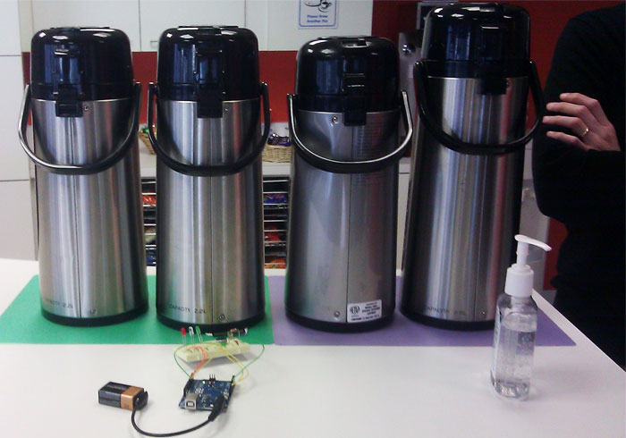
If your office is like mine then coming into the kitchen just to find the coffee pot empty and no one has refilled it drives people crazy. Well not anymore with this simple coffee pot alarm. Really this is a simple exercise in using a FSR or Force Sensitive Resistor. By using a simple sensor we can measure the force or basically weight of the coffee pot.
What we’re doing here is simply returning a value between 0 and 1024 from the FSR and when the value falls within one of our specified ranges activates an led or combination of led and buzzer. Let the fun begin.
What You’ll Need:
- Arudino
- Force Sensitive Resistor
- Jumper Wires
- 1 Red Led, 1 Orange Led, 1 Green Led
- Piezo Buzzer
- 10k ohm resistor
- 9V batter and connector optional
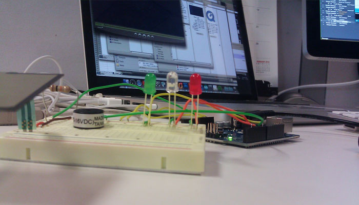
Here I have my Led’s set as digital outputs with pin 2 = red, pin 4 =orange and pin 7 =green. My buzzer is an analog output on pin 5. Our FSR is also an analog reading on A0. Once you’re ready to go be sure to launch your Serial Monitor (Tools >Serial Monitor) to get text feedback during testing. As you squeeze the sensor we’ll go from “No pressure Getting Refilled” for when the coffee pot has been removed from the sensor to “Coffee Full!” when the pot has been refilled. You may need to adjust your values depending on the weight of your coffee pot at various levels. The FSR I’m using has a max weight of 22 lbs and many are around the 20 lb range.
This project is completely Arduino based. Here’s the code:
/* FSR simple coffee pot alert.

Connect one end of FSR to power, the other end to Analog 0.
Then connect one end of a 10K resistor from Analog 0 to ground

For more information see www.ladyada.net/learn/sensors/fsr.html */

int fsrPin = 0;     // the FSR and 10K pulldown are connected to a0
int fsrReading;     // the analog reading from the FSR resistor divider
int LEDR = 2;       //Red Led
int LEDO = 4;       //Orange Led
int LEDG = 7;       //Green Led

void setup(void) {
  // We'll send debugging information via the Serial monitor
  Serial.begin(9600);
 pinMode(LEDR, OUTPUT);
 pinMode(LEDO, OUTPUT);
 pinMode(LEDG, OUTPUT);
 pinMode(5, OUTPUT);    //Piezo buzzer
}

void loop(void) {
  fsrReading = analogRead(0);

  Serial.print("Analog reading = ");
  Serial.print(fsrReading);     // the raw analog reading

  // We'll have a few threshholds, qualitatively determined
  if (fsrReading < 10) {
    Serial.println(" - No pressure Getting Refilled");   //writes to serial monitor, be sure to open it
    refill();             //function that cycles leds written below
    digitalWrite(5,LOW);
  } else if (fsrReading < 200) {
    Serial.println(" - Empty");
    digitalWrite(LEDR, HIGH);    //Turns Red Led on
    analogWrite(LEDO, LOW);
    analogWrite(LEDG, LOW);
    analogWrite(5,50);          //sounds buzzer, range can go up to 256, but set to 50 so not to loud
  } else if (fsrReading < 500) {
    Serial.println(" - Getting Low");
    analogWrite(LEDR, LOW);
    digitalWrite(LEDO, HIGH);   //Turns Orange Led on
    analogWrite(LEDG, LOW);
    digitalWrite(5,LOW);
  } else if (fsrReading < 850) {
    Serial.println(" - Enough Coffee");
    analogWrite(LEDR, LOW);
    analogWrite(LEDO, LOW);
    analogWrite(LEDG, LOW);
    digitalWrite(5,LOW);
  } else {
    Serial.println(" - Coffee Full!");
     analogWrite(LEDR, LOW);
     analogWrite(LEDO, LOW);
     digitalWrite(LEDG, HIGH);   //Turns Green Led on
     digitalWrite(5,LOW);
  }
  delay(1000);
}


//Function that runs when no pressure is registered to cycle leds
void refill() {
  digitalWrite(LEDR, HIGH);
  delay(100);
  digitalWrite(LEDR, LOW);
  delay(100);
  digitalWrite(LEDO, HIGH);
  delay(100);
  digitalWrite(LEDO, LOW);
  delay(100);
  digitalWrite(LEDG, HIGH);
  delay(100);
  digitalWrite(LEDG, LOW);
  delay(100);
  digitalWrite(LEDR, HIGH);
  delay(100);
  digitalWrite(LEDR, LOW);
  delay(100);
  digitalWrite(LEDO, HIGH);
  delay(100);
  digitalWrite(LEDO, LOW);
  delay(100);
  digitalWrite(LEDG, HIGH);
  delay(100);
  digitalWrite(LEDG, LOW);
  delay(2000);
}
While the circuit may look a little busy, remember the two lower breadboard rows are 5V and ground running horizontally on the board. This is a rough demonstration so I'm sure you can make it much neater if your going for a finished product. The code is a great jumping off point for other projects as well so get creative and try to add other sensors.


No Comments